Motor Power
Just like any electrical device, motors draw current and consume a certain amount of power to function. Motors convert some portion of the input power into spinning the shaft; this portion is the output power. Thinking of motors in terms of energy instead of speed and torque can make it easier to calculate how it should be used and provide tools for choosing the optimal gear ratio for an application.
What is Power?
Fundamentally, power is defined as the amount of energy transferred in a given time period. Practically, this means power is how much “energy” you can get out of the motor. The output power of a motor varies depending on how much load is on it, but does not change as the gear ratio of the motor changes. What this means is that a free-spinning 1:1 motor will output the same amount of power as a free spinning 100:1 motor (ignoring friction differences), but the actual speed and torque will be different. Output power is proportional to speed times torque, so as speed and torque are changed with a gearbox, the output power must remain the same.
Another piece of information, although not always as useful, is the input power of the motor. The input power of the motor is how many watts of power the motor consumes, which is equal to the voltage sent to the motor times the current consumed by the motor. Motors are not 100% efficient, so to get a certain output power you often need double or even triple the input power. For example, a standard FTC® motor can consume up to 65 watts just to produce 29 watts of output power.
Peak Power and Motor Curves
In order to figure out how much power your motor will be consuming or outputting, its helpful to reference a motor curve. These are data sheets that plot the motor’s output speed, output torque, output power, and efficiency all on one graph. Every FTC legal motor except the Core Hex has been dyno tested, and their data are below. It is safe to assume other non-current limited motors (such as servos) follow similarly-shaped curves, although with different speed, torque, and power outputs.
Free Speed (RPM) |
Free Current (A) |
Maximum Power (W) |
Stall Torque (N*m) |
Stall Current (A) |
|
|---|---|---|---|---|---|
goBILDA (MATRIX) |
5900 |
0.3 |
29 |
0.19 |
11 |
NeveRest |
5500 |
0.4 |
26 |
0.17 |
9.8 |
REV Core Hex[1] |
125 |
0.2 |
10 |
3.2 |
4.4 |
REV HD Hex |
6000 |
0.3 |
28 |
0.18 |
11 |
TorqueNado |
5900 |
0.2 |
26 |
0.17 |
9.8 |
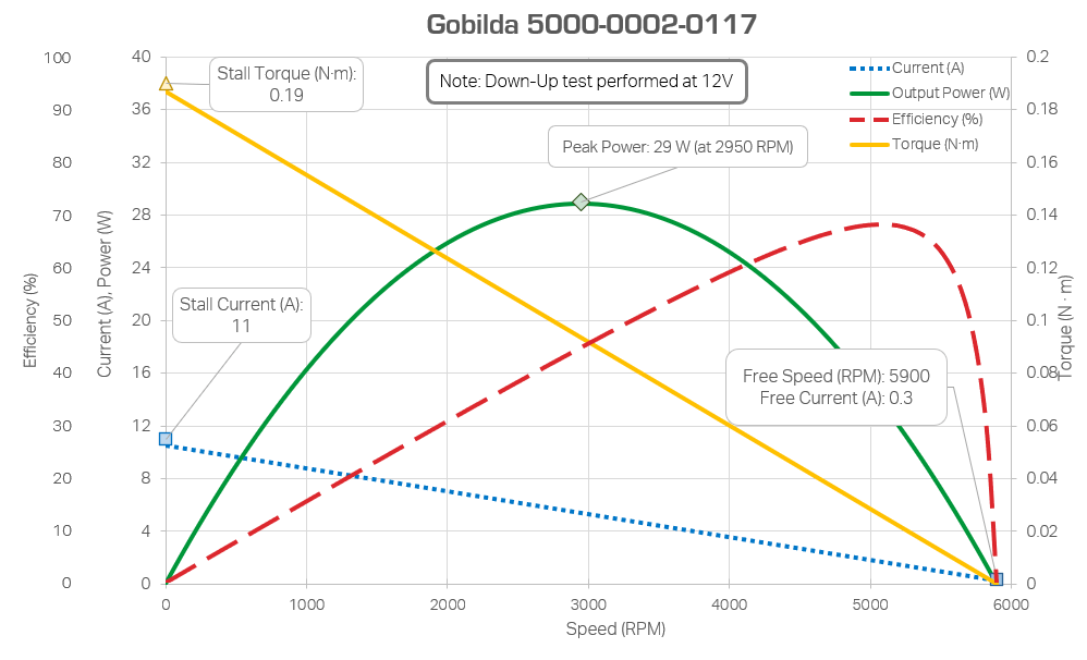
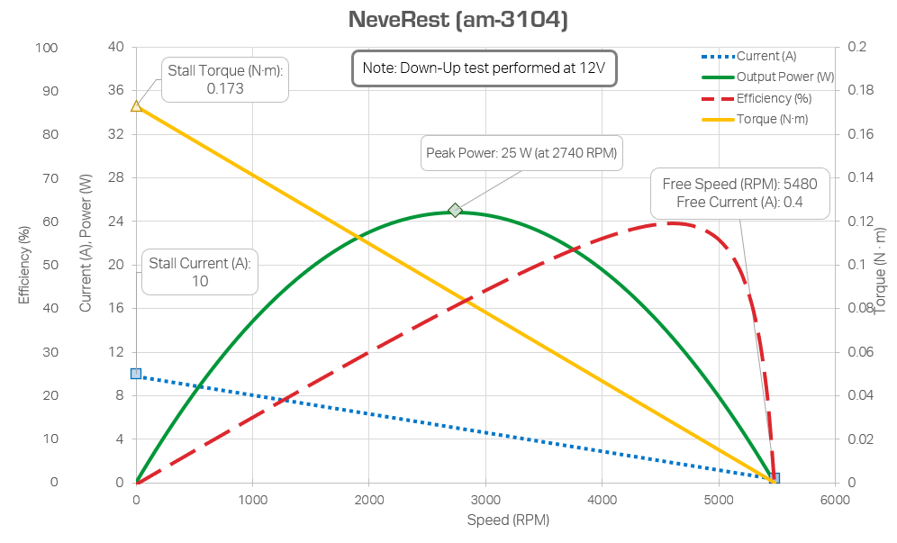
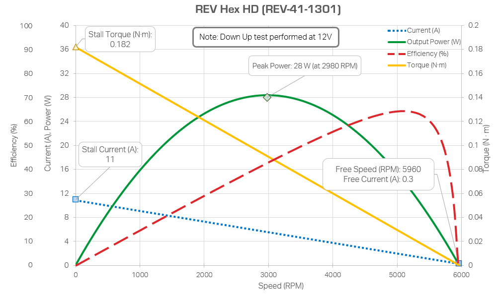
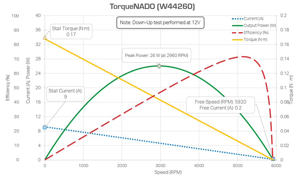
A motor curve represents a motor at 12 V (equivalent to setting the motor power to 1 in software) with various amounts of load applied to the axle. As you can see, the power output from the motor is not constant, instead rising until about 50% load, before falling again. This point at 50% load is called the peak power output of the motor, and is at a similar point (50% load) across all FTC legal motors.
The varying power of a motor means that speed and torque output do not change linearly when more load is applied onto the axle. Counterintuitively, placing 50% stall load on a motor doesn’t halve its speed, but will rather reduce it to slightly above 50% speed. Similarly, placing more then 50% load on a motor will cause the speed to fall faster then linearly.
In addition, you can see that efficiency rises as speed goes up. This means, if current draw is a concern, one should always be running their motors with loads below 50% of their stall torque. These two properties of a motor, the peak power output being 50% of the stall torque and the efficiency of a motor being higher the lower the load is, guide the selection of the gear ratio of a motor. Ideally, gear ratios should be chosen such that the stall torque is twice the average torque load on the motor, and should skew towards providing more torque than needed rather then less.
Note on Current Consumption
You may see while looking at motor curves that the stall current of FTC motors can be as high as 11 amps per motor. FTC batteries can only provide 20 amps of current output before blowing the fuse is likely. However, even if the 20 amp limit isn’t reached, drawing too much current can cause other motors to feel sluggish or unresponsive. Care should be taken to ensure that more than two motors are never stalled at the same time.
Note
You may be able to ignore this when dealing with mecanum drivetrains, as they will generally slip before the motors actually reach their stall current. However, placing very low gear ratios or more than 4 motors on traction drivetrains can exceed the current limit of an FTC battery.
Motors can pull “transient current” where they pull a large amount of current for extremely brief amounts of time. This often happens when the motor starts moving or when a momentary load is placed on it. While transients generally cannot cause a fuse to pop, they can cause other issues, such as sluggish control if pulled by a motor, or low voltage if the transient is pulled by a servo (goBILDA Super Speed servos have been observed to do this occasionally).